Technical Information – Industrial Products Castor Types
In general, industrial castors can be sub-divided into two main types:
a) Pressed Steel – typical pressed steel type castors incorporate single and double ball race constructions. The balls run in tracks formed in the fork and top plate pressings which are secured together by a heavily riveted steel king pin.
b) Fabricated Steel – these usually consist of heavy steel forgings which are precision machined and house combinations of tapered roller bearings or ball races. The fork legs are securely welded to the body forging giving an extremely strong construction suitable for extra heavy loads.
Castor UsesCastor applications can be divided into two main categories:
a) Castors for use on trucks, trolleys, trailers, etc. which are used as a means of transportation and regularly moved from one place to another.
b) Castors fitted to a machine or other device to enable it to be delivered to the place where it is used to enable it to be moved occasionally for very short distances
In the case of (a) it is essential that castors should have the lowest tractive resistance and should be able to swivel freely so that the trolley can be manoeuvred without too much effort. To achieve this, wheels should be at least 100mm diameter and preferably 150mm or more, regardless of the rated capacity. For category (b) smaller castors may be acceptable and are often used at their full rated capacity.
Castor Terminologya) Swivel castors – an assembly in which a housing containing a wheel is free to swivel without restriction about the vertical axis of the swivel bearing with the castor wheel axle offset.
b) Fixed castors – an assembly housing a wheel which cannot swivel about its vertical axis
c) Wheels – a revolving centre rotating freely on an axle of which the external part (in contact with the ground) can be constituted by the material of the wheel itself or by various other materials.
d) Offset – the horizontal distance between the centre of the wheel axle and the vertical axis of the swivel bearing: this may sometimes be known as trail.
e) Tractive resistance – the effort required to move a piece of equipment fitted with castors: this is usually expressed as a percentage of the total load carried
Interpretation of Catalogue Load Ratings
Great care has been taken in choosing ratings which will ensure satisfactory life, performance and ability to withstand reasonable abuse under normal conditions.
There are, however, many occasions when it is necessary to under rate castors to ensure the correct degree of mobility for the unit.
When castors are fitted to a trolley which is regularly used for transportation of goods or products, it is necessary to specify a minimum of 150mm wheel diameter and choose swivel heads for this type of application.
When castors are to be fitted to a piece of equipment for occasional movement, it is often possible to use quite small castors provided they have sufficient load capacity.
Castor and Wheel SpecificationAll dimensions and load capacities are, unless otherwise stated, in metric i.e. mm and kgs. In some cases, wheel diameters are displayed in inches in addition to mm if it is significant to the castor code, i.e. KV6SUB indicates a KV castor with a 6” or 150mm wheel.
Code Numbers of CastorsThe online catalogue details products from different brands: Colson Castors UK, British Castors, Flexello Castors, and Global Castors etc. For details of specific part numbers please refer to the detailed descriptions shown.
Castor LoadingsWorking conditions for castors may vary enormously both with regard to the type of floor and also the severity of the actual application. Average working conditions are typified by many factors where one or more hazards (e.g. overloading and shock loading are possible, the floor may not be reasonably level and may contain cracks, gullies, door guide rails etc. and the floor surface may be of an abrasive nature), may be present to a limited degree. Although there are many variables in the selection of the correct castor for the particular application, the total load to be carried on the castors is generally known. It must be appreciated, however, that load capacity is not the only factor to be considered in choosing castors for a specific job. It may often be necessary to choose a castor having given a load capacity several times greater than the conditions appear to warrant ensuring that the castors are capable of giving the desired performance. The factory should be consulted if there is any doubt that a castor or wheel is capable of providing the desired performance.
Correct Alignment of Fixed and Directional Lock Castors
In accordance with the relevant ISO standard, top plate fixing holes have a working clearance of 1mm for all bolts up to 12mm, and 2mm for larger sizes. This accommodates minor positional errors in the manufacture of the trolley but also allows the castors to be misaligned to the point where drag and tyre wear could be excessive. It is therefore necessary to align the castors correctly before the bolts are finally tightened.
Wheel SelectionFor manual applications the choice of correct castor wheel is very closely related to the effort which a person can exert. In choosing the type of wheel to specify consideration should be given to tractive resistance, which is normally expressed as a percentage of the total load carried, and is dependent on a number of factors and will vary for each application. In general terms wheels can be divided into two main types:
a) Resilient Tread Wheels
b) Hard Tread Wheels
Resilient Tread WheelsResilient or Soft Tread Wheels, such as rubber or polyurethane, offer quietness and floor protection but may limited ease of movement as the tractive resistance or effort required to move them is generally up to three times greater than that of the equivalent hard tread wheels. Polyurethane has the property of being able to carry loads approaching that of cast iron and has a great resistance to tearing and to abrasive wear (many time the life of rubber). It also has a lower tractive resistance than rubber for the same load and is impervious to mineral oils and greases. For many high load applications soft tread wheels must be ruled out as, although they are capable of carrying a very high load the force required to move the equipment would require the efforts of several persons. However, the quiet running and floor protecting properties of the resilient tread wheels make them particularly suitable for power towing applications.
Hard Tread WheelsIn the range of hard tread wheels it is usual to consider castors with cast iron wheels as a basic standard as these are generally the strongest and have the longest life. They are the easiest to push and will, in many cases be the first choice for maximum mobility. They have the disadvantage, however, of being noisy and can sometimes cause excessive floor wear.
Injection moulded solid nylon wheels are an alternative to cast iron; nylon is unaffected by water and its use in the wet further enhances its self-lubricating properties. The load capacity of nylon approaches that of cast iron and these wheels also have the additional advantages of being quiet running, light in weight and almost incapable of damaging floors. They can be used in the temperature range -40°C to 80°C, although it may be necessary to derate the load capacity of the wheels by up to 25% for very arduous conditions. For higher temperature applications reinforced phenolic wheels are also available.
Castor Wheel Configurations
a) 2 Swivel Castors and 2 Fixed Castors
The most practical configuration for industrial use. This solution provides good load capacity with good manoeuvrability and ensures accurate steering, even on long straight runs. The trolley should normally be pushed with the fixed castors leasing.
Maximum capacity = load for each wheel 3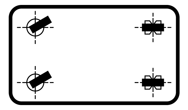
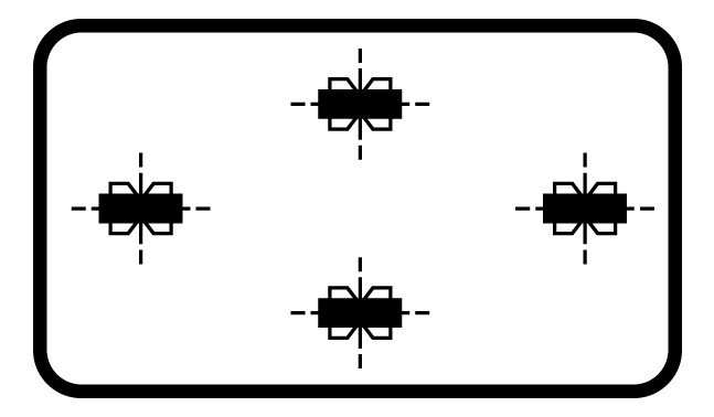
b) 4 Swivel Castors
This arrangement provides goad load capacity with excellent manoeuvrability, suitable for winding runs and where side motion is frequently required. trolleys with this configuration may be difficult to guide on straight runs, particularly with heavy loads and uneven ground. Not recommended for ramps. If two castors are equipped with directional locks, this arrangement is then suitable for long runs.
Maximum capacity = load for each wheel 3.png)
c) 1 Swivel Castor and 2 Fixed Castors
An economical solution for lightly loaded trolleys requiring good manoeuvrability. The trolley must be fairly small in size and it is essential that the load is evenly distributed to ensure stability on the unit.
Maximum capacity = load for each wheel 3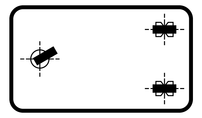
d) 3 Swivel Castors
The arrangement provides good load capacity with excellent manoeuvrability. Equipment with this arrangement will be difficult to guide on straight runs particularly over uneven ground. This configuration is ideal for barrel dollies and small portable machines.
Maximum capacity = load for each wheel 3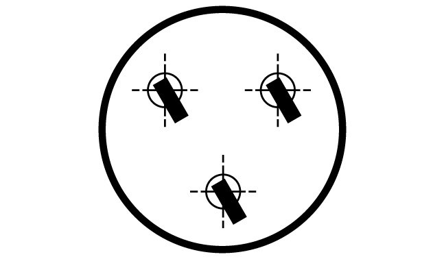
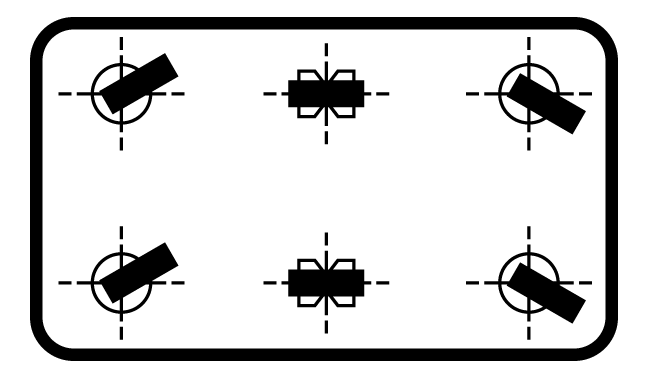
e) 4 Swivel Castors and 2 Fixed Castors Centrally Pivoting
Besides providing a very high load capacity, this arrangement also offers enhanced manoeuvrability and stability. This configuration is best used with very long trolleys designed to carry heavy loads. The fixed castors can be replaced by wheels mounted onto a central axle. The base of the unit must be of a robust construction. The swivel castors are mounted in such a way as to pivot the trolley on the central wheels, it is usual to put approximately 25mm of packing above the two fixed castors (wheels) and thus provide alternating load support, depending on which pair of wheels are in contact with the floor. However, the swivel castors are subject to shock loads if the trolley is tipped or the load is not evenly distributed. The entire load rests on the two central, fixed castors/wheels.
Maximum capacity = load for each wheel 2
f) 4 Fixed Castors Centrally Pivoting
An economic solution for moderate loads suitable for long, straight runs with occasional changes in direction. The fixed castors can be replaced by wheels mounted onto a central axle. The two end castors are mounted in such a way as to pivot the central wheels, it is usual to put 25mm of packing above the two fixed castors (wheels) and thus provide alternating support. However, the end castors are subject to shock loads if the trolley is tipped or the load is not evenly distributed.
Maximum capacity = load for each wheel 2
Power Towing Applications
All of our pressed steel castors are designed specifically for manual propulsion. Due to greatly increased stresses exerted on various components on castors in power towing, our pressed steel castors are not recommended in power towing applications.
In the case of fabricated castors, the load capacities are much higher and it is obvious that power towing must be the norm. The castors are therefore designed on the assumption that power towing will take place but at a maximum of 7kph and under good working conditions. Obstructions such as curbs and gullies and even relatively small steps, can exert enormous impact loads that can destroy a castor. Steps such as lift sills, drain covers and joints in concrete slabs present a particular problem if they are not approached squarely. An oblique approach will almost certainly result in the castor turning at right angles to the obstruction instead of turning in such a way that it can climb over it. In these circumstances the destruction of the castor is inevitable.
Towing trailers in train exacerbates the problem as only one castor may have to withstand the force generated by the mass of the whole train including the tractor.
It is often desirable to tow a number of trucks or trailers one behind another. Traditional turntable axles have often been used for this purpose but in addition to being costly they have two disadvantages: if the turntable is at right angles to the axis of the trucks the stability is drastically reduced; there is a risk of jack-knifing if the trailers stop on a sharp corner.
Castors are a popular option for this application and work satisfactorily provided suitable precautions are taken. It is essential to obviate ‘cutting in’ as this would prevent the use of the truck trains in narrow gangways. Experience has shown that if trucks are rigidly coupled together by means of pin couplings at each end they will follow the track most accurately if the distance from the fixed castor centre line to the rear coupling pin is 25%-33% of the total length of the truck from front to rear coupling pins.
This can be achieved by moving the fixed castors forward but this incurs a penalty in that it reduces the wheelbase of the trucks and also causes the total weight to be shared disproportionately between the swivel castors and the fixed castors.
In order to distribute the weight of the truck and its contents evenly between the front swivel and rear fixed castors it is advisable to extend the drawbar at the rear of the truck.
The Flexello EH and EHF Series castors of 1, 2, 3 and 5 tonne nominal capacity are specifically designed for power towing, having tapered roller bearings in both the swivel heads and wheels, and will operate satisfactorily at speeds up to 7kph under the given loads. KV and KVF Series castors are also available with tapered roller bearing wheels for power towing applications.
Top Plate Bolt Hole Centres
ISO 22882:2004 sets out a range of standardised fixed hole centres as follows:
R42 – 80mm x 60mmR43 – 105mm x 80mm
R44 – 140mm x 105mm
Wherever possible our castors conform to the above standard. In some cases the plates are already slotted to accommodate alternative hole centres such as those to DIN standards and to standards used throughout the United States. Wherever possible customers are advised to conform to the ISO standards and always to avoid placing bolts anywhere except at the ends of the slots.
Swivel Head Seals
Swivel head seals are fitted as standard on EH, KV, GT, SL and 22 Series castors. The seals are produced in polypropylene nylon and glass filled nylon, and are effective over the temperature range from -40°C to 100°C.
Head seals effectively reduce maintenance to a minimum but EH, GT and SL castors are fitted with grease nipples for replenishment purposes under arduous working conditions.
Directional Locks
We offer 2-way directional locks on certain castors as opposed to 4-way locks. If 4-way locks are fitted and a trailer is moved with the automatic locks in ‘on’ position but not engaged when the castors are facing the wrong way, they will almost inevitably lock automatically as the castor swivels through the 90° position. This will in effect brake the trailer and could cause a sudden swerve injuring anyone in the way. If 2-way locked castors are fitted, they will function exactly as before but without risk of locking in the 90° position. We will supply 4-way locks for special applications when we are satisfied that the customer understands the risks involved and knows the limitations in the use of these castors.
Truck Locks
These are specifically designed to steady the equipment to which they are fitted and prevent horizontal movement. They are never intended to act as a jack and any attempt to vary the fitting height from the catalogue specification must result in failure and/or damage. In each case there is a degree of built-in resilience in the foot pad and in the case of the TLCH there is an additional compression spring. This will, to a certain degree, accommodate variations in floor level, but it is still essential to fit the truck lock as close as possible to one of the swivel castors. The truck lock can be severely damaged if the linkage is operated whilst the truck is moving.
EH and KV Series, Adjustment of Tapered Roller Bearings
The bearings are correctly adjusted when the castor is built and should never require attention other than possibly greasing, if the conditions are particularly arduous. Tapered roller bearings in swivel heads are deliberately pre-loaded as this eliminates any risk of damage even in conditions of severe abuse. No attempt should be made to strip down or re-adjust these bearings.
Tapered roller bearing in wheels are set up with a predetermined amount of axial clearance in exactly the same way as with road vehicle front hubs, and should never require re-adjustment. If however, a wheel has to be replaced due to abuse or accidental damage, it is essential that the wheel is correctly set up with absolutely no risk of any pre-load of the bearings. In the absence of dial indicator gauge (the correct measuring instrument) it is difficult to judge the degree of axial clearance, which should not exceed 0.1mm. As with a bicycle front hub, it is possible to judge this reasonably accurately by feeling the amount of ‘rim-rock’ at the head of the wheel. If in any doubts please consult the factory.
Wheels used in applications other than castors
All of our wheels are designed to have the axle supported at both ends, i.e. in a castor fork.
An axle supported at only one end (i.e. as a cantilever) will have insufficient diameter to resist the bending moment at our full load rating. If cantilever axles are specified by the customer, it must be his responsibility to choose a lower load rating for the wheel, taking into account the working conditions and the safe stress limit for the material from which the axle is made.
EXPANDERS
Standard Range Expanders Fitting Instructions
- Assemble Expander
- Assemble the bolt to the castor so that bolt head is inside the castor assembly ie the thread is protruding from the top of the castor.
- Slide the washer over the bolt.
- Slide the bottom cone (plain hole) over the bolt so that the smaller square end is facing up.
- Slide the sleeve over the bolt, the sleeve is the same at each end so orientation is not required. Align the flats on the bottom cone with the flats on inside of the sleeve.
- Screw the top cone (threaded hole) down the thread so that the small square is now towards the sleeve. Screw down until sleeve and cone contact, at this point align the square of the cone with the square of the sleeve, slide sleeve up and continue to screw down so that sleeve and cones rotate together and are in line but loose and ready for assembly into the tube
Heavy Duty Range Expanders Fitting Instructions
- Assemble Expander
- Assemble the bolt to the castor so that bolt head is inside the castor assembly ie the thread is protruding from the top of the castor.
- Slide the washer over the bolt.
- Slide the bottom cone (plain hole) over the bolt so that the smaller square end is facing up.
- Slide the sleeve over the bolt, orientation of the sleeve is required so that the inner square matches the small square of the bottom cone and the large square matches the out side of the sleeve.
- Screw the top cone (threaded hole) down the thread so that the small square is now towards the sleeve. Screw down until sleeve and cone contact, at this point align the square of the cone with the square of the sleeve, slide sleeve up and continue to screw down so that sleeve and cones rotate together and are in line but loose and ready for assembly into the tube.
Fixing the Expander
Offer the castor with expander assembly up to the tube and if using square tube, aligning flats of expander with flats of tube. Push expander assembly fully home ie the castor is in contact with base of tube. Tighten bolt to a maximum of 10Nm for M12 bolt and 8Nm for M10 bolts ensure castor is securely fitted.
Chemical Resistance of Wheels
The table below gives a general ‘rule off thumb’ guide to the resistance of our wheels to certain chemicals and oils. The resistance is graded on a scale of 1 to 6 with 1 being high resistance and 6 being low resistance. The resistance to corrosion indicated in the table refers to a wheel being immersed in the chemical for a prolonged period. In the case of splashes or very short periods of exposure the expected life of a wheel may be extended although it is suggested that you contact our factory for further information if in any doubt.
| Chemical Resistance of Wheels | |||||||||
| WBS | WRT |
WPS |
WRN | WSU | WPN | WNY | WED | WCI | |
| Acetic acid (50%) |
5 |
6 | 5 | 5 | 6 | 4 | 4 | 1 | 6 |
| Acetone | 6 | 1 | 6 | 6 | 6 | 6 | 1 | 1 | 1 |
| Ammonia solution (weak) | 5 | 3 | 3 | 3 | 3 | 3 | 3 | 1 | 1 |
| Bleach solution | 2 | 4 | 3 | 3 | 4 | 4 | 3 | 1 | 1 |
| Butanol | 6 | 6 | 6 | 6 | 3 | 3 | 1 | 1 | 1 |
| Carbon Tetrachloride | 6 | 5 | 5 | 5 | 4 | 4 | 1 | 4 | 1 |
| Diesel oil | 4 | 4 | 4 | 4 | 3 | 3 | 1 | 3 | 1 |
| Edible oils | 2 | 2 | 2 | 2 | NDA | NDA | 1 | 1 | 1 |
| Ethanol | 5 | 5 | 5 | 5 | 4 | 4 | 1 | 1 | 1 |
| Hydrochloric acid (up to 30%) | 6 | 6 | 6 | 6 | 6 | 4 | 4 | 1 | 6 |
| Hydrofluric acid (up to 40%) | 6 | 6 | 6 | 6 | 6 | 5 | 5 | 1 | 6 |
| Hydrogen peroxide (30%) | 2 | 5 | 5 | 5 | 6 | 5 | 5 | 2 | 6 |
| Hydrogen sulphide | NDA | 2 | 2 | 2 | 4 | 4 | 2 | 1 | 1 |
| Machine oil | 6 | 6 | 6 | 6 | NDA | NDA | NDA | 1 | 1 |
| Methanol | 6 | 6 | 6 | 6 | 6 | 6 | 2 | 1 | 1 |
| Mineral oils | 6 | 5 | 2 | 2 | 1 | 1 | 1 | 1 | 1 |
| Motor oils | 6 | 6 | 6 | 6 | 3 | 3 | NDA | 1 | 1 |
| Nitric acid (10%) | 6 | 6 | 6 | 6 | 6 | 6 | 6 | 1 | 6 |
| Paraffin | 3 | 1 | 1 | 1 | NDA | NDA | 1 | 1 | 1 |
| Petrol | 6 | 6 | 6 | 6 | 2 | 2 | 1 | 4 | 1 |
| Phosphoric acid (10%) | 6 | 6 | 6 | 6 | 6 | 6 | 6 | 1 | 6 |
| Seawater | 1 | 1 | 1 | 1 | 3 | 1 | 1 | 1 | 1 |
| Soap solution | 1 | 1 | 1 | 1 | 2 | 2 | 1 | 1 | 1 |
| Sodium bicarbonate | 1 | 1 | 1 | 1 | 2 | 2 | 1 | 1 | 1 |
| Sodium hydroxide solution (10%) | 2 | 1 | 1 | 1 | 2 | 2 | 1 | 1 | 1 |
| Sulphuric acid (up to 50%) | 4 | 6 | 6 | 6 | 6 | 6 | 6 | 1 | 6 |
| Trichloroethylene | 6 | 6 | 6 | 6 | 5 | 5 | 2 | 4 | 1 |
| Water | 1 | 1 | 1 | 1 | 2 | 2 | 1 | 1 | 1 |
| White spirit | 2 | 4 | 4 | 4 | NDA | NDA | 2 | 3 | 1 |